The ILS installation is made up of several components. You recieve guidance information from ground-based localizer and glide slope transmitters. To help you determine your distance from the runway, the ILS installation may provide DME fixes or marker beacons located along the ILS approach path. Here’s the breakdown.
Localizer
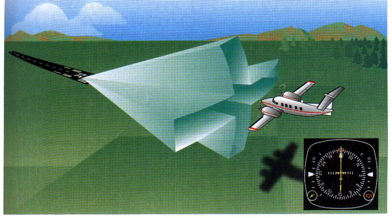
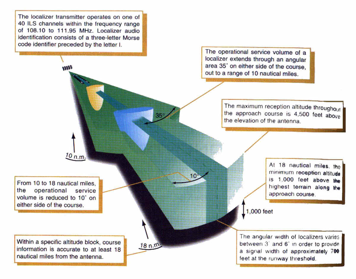
This provides the information regarding your alignment with the runway centerline. When using a basic VOR indicator, normal sensing occurs inbound on the front course and outbound on the back course. Reverse sensing occurs inbound on the back course and outbound on the front course. With an HSI, you can avoid reverse sensing by setting the published front course under the course index. This applies regardless of your direction of travel, whether inbound or outbound on either the front or back course.
Glide Slope
The glide slope gives you vertical guidance on the final approach course.
The rate of descent you should maintain primarily depends on your groundspeed. For the same glide slope angle (usually 3°), you will need a lower rate of descent as your groundspeed decreases, and vice versa. If you maintain the glide slope for an approach, you should reach the decision height at approximately the middle marker. Although you may reach the decision height at or near the middle marker, the charted MAP for an ILS approach is the point where the glide slope intercepts the decsion height. This point may or may not be at the middle marker.
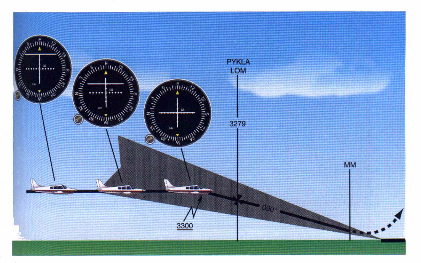
Since your aircraft is usually below the glide slope during the intermediate approach segment, the glide slope indicator will display a full-up needle deflection. You should observe the initial downward movement of the indicator and lead the descent to intercept the glide slope centerline accordingly.
Now put it all together
When flying an ILS, you track the line formed by the intersection of the glide slope and localizer courses.